|
LINKS
Car Load Modeling Estimates 7/25/2010 |
Model Railroading Main Page Here you
will find links to LIRR and other rail line modeling via prototype and
model photos, maps, charts and
|
|
|
|||
| Modeling Amityville | |||
 |
 |
 |
Published in
The CANNON BALL Fall 2024 |
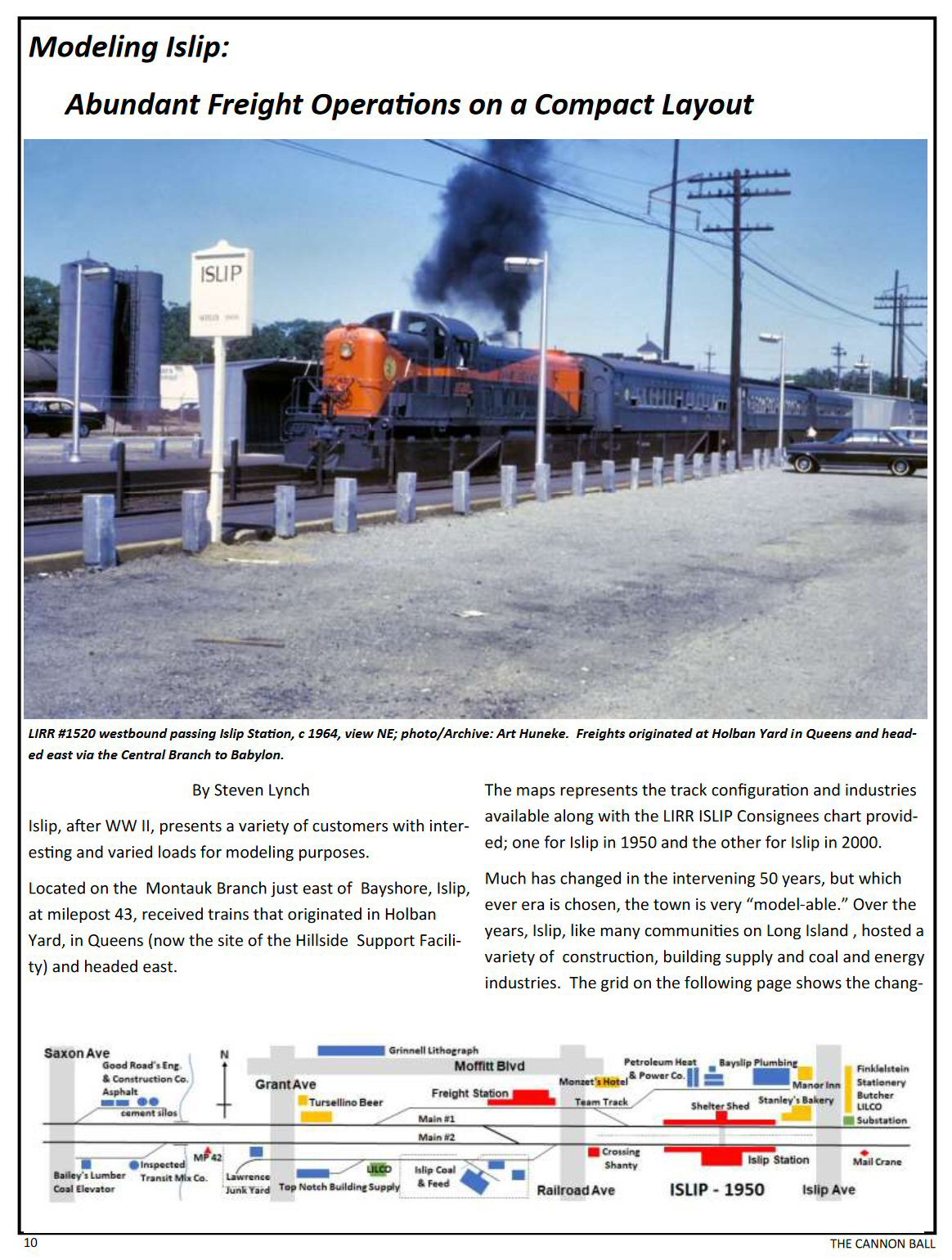
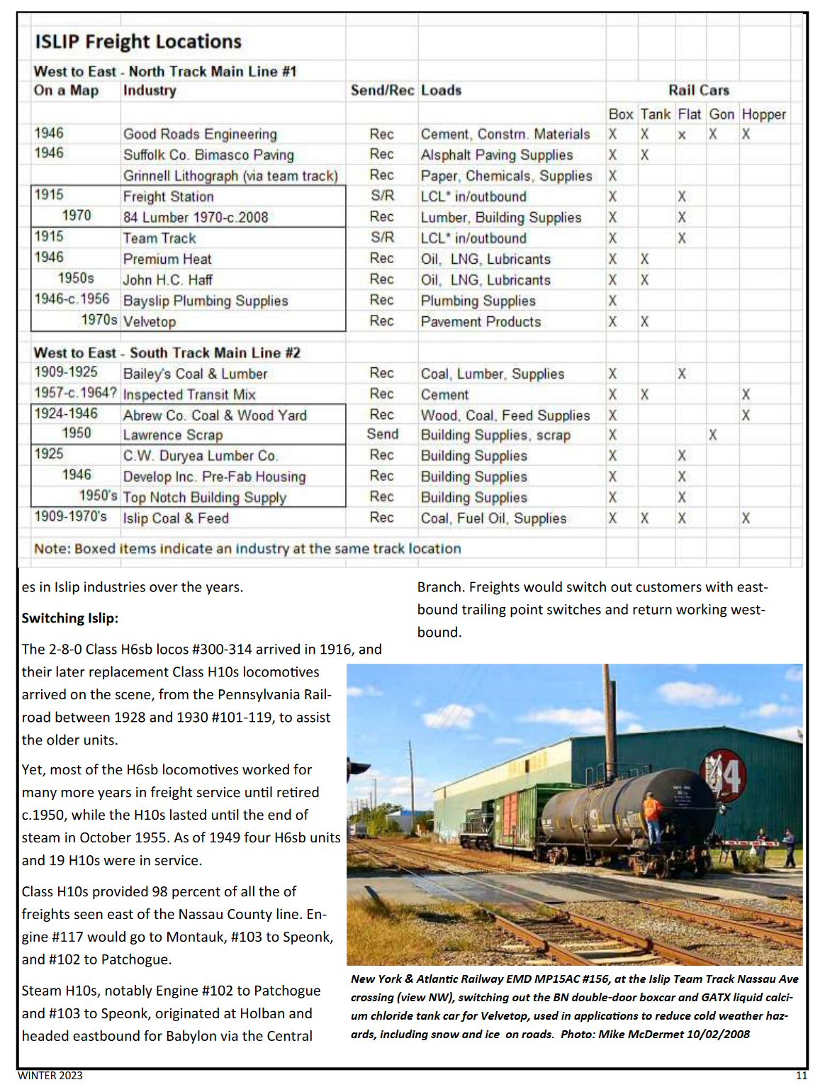
| Modeling Islip | |||
 |
 |
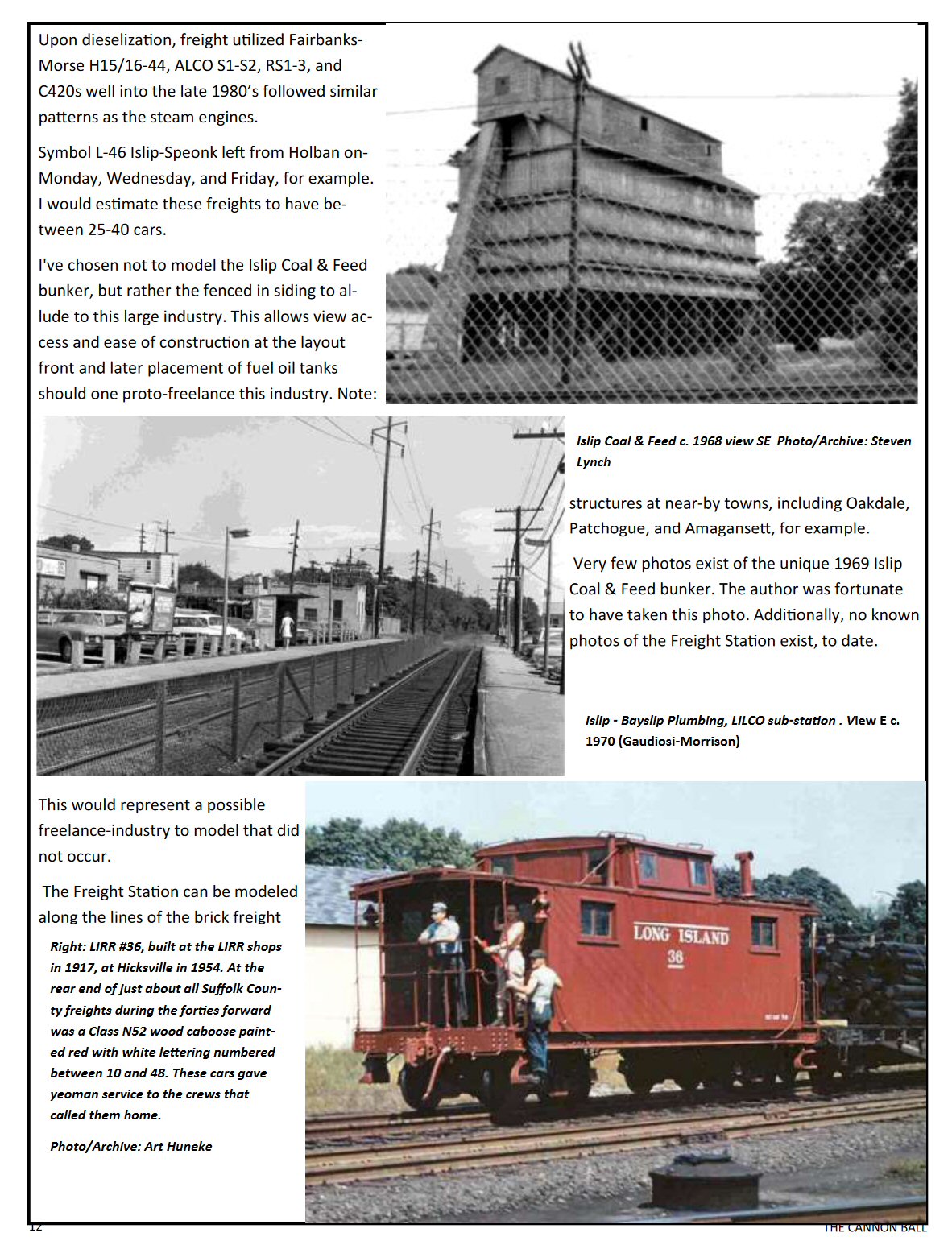 |
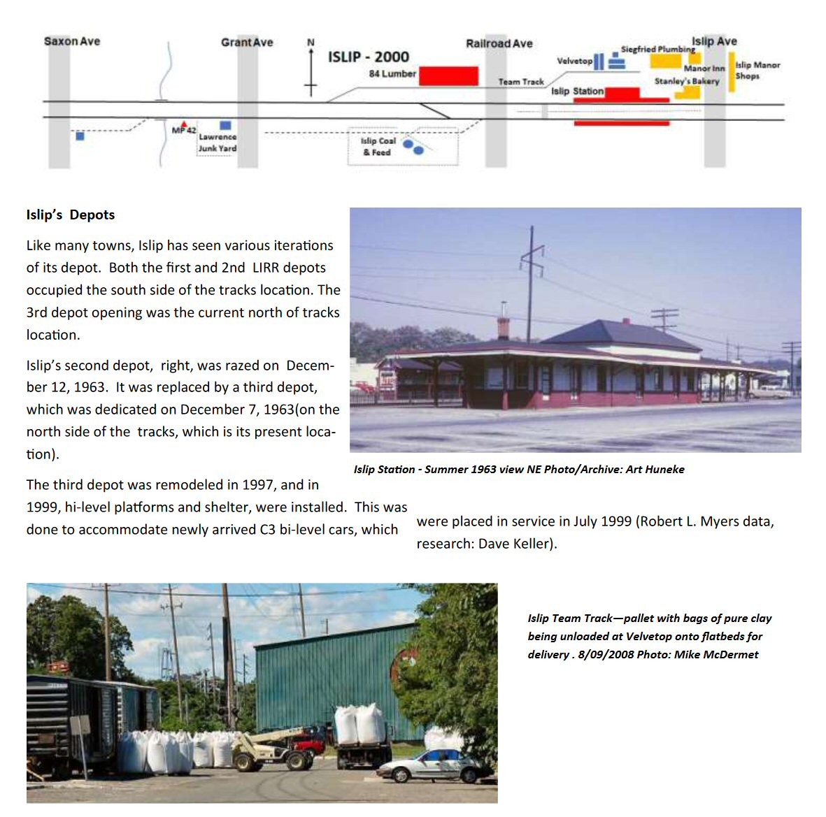 Published in The CANNONBALL Winter 2023 Sunrise Trail Division, Northeast Region NMRA by Steven Lynch |
| (Op SIG) LIRR Industry List | Patchogue Section House | Canvas Tarps | |
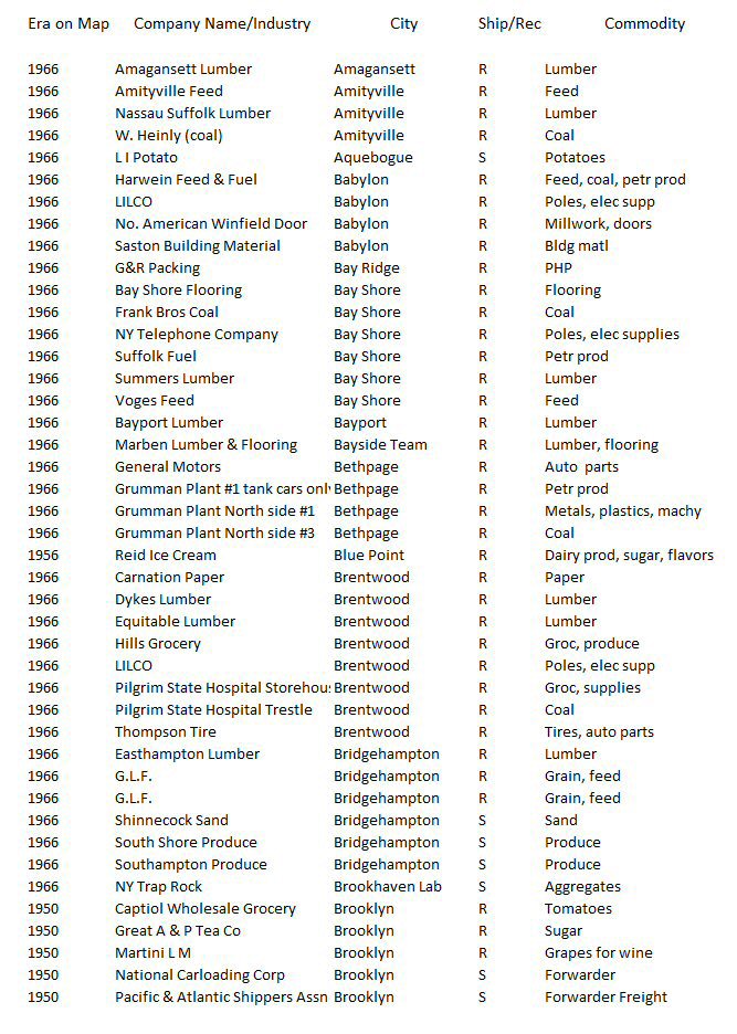 Op Sig Group - LIRR Industry List |
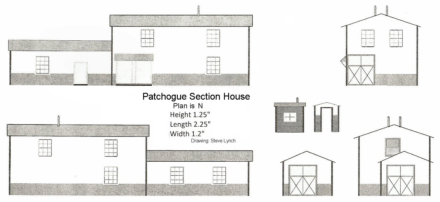 Patchogue Section House diagram - Design/Archive: Steven Lynch |
 Discarded plastic blister pack brushed with 50% water/white glue mix. Apply tissue paper and let dry. Brush paint acrylic tarp color; in this case Sandstone. Photos/Archive: Steven Lynch |
|
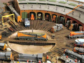
| Yard A - LI City | |||
|
|
|||
| LIRR Ready To Run and Kit Models | |||
|
The
UPDATED
LISTS (9/06/2023) are a work in progress as new LIRR models are produced and information is
added/updated/modified. Welcome are corrections/additions/modifications to these LIRR listings. Created by: Timothy Howell |
|||
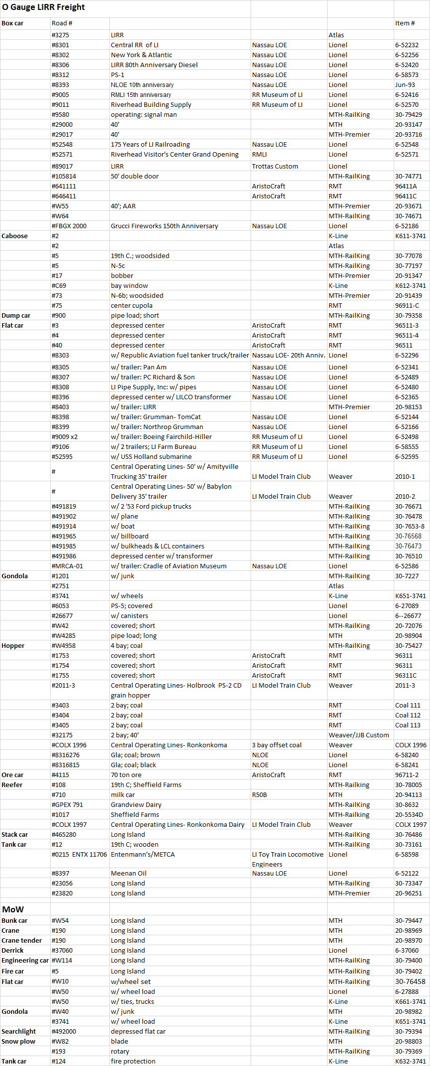 O LIRR - Freight & MOW |
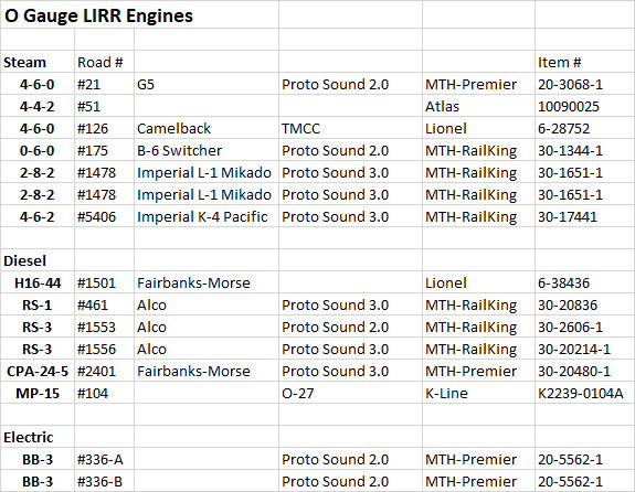 O LIRR - Steam, Diesel, & Electric
|
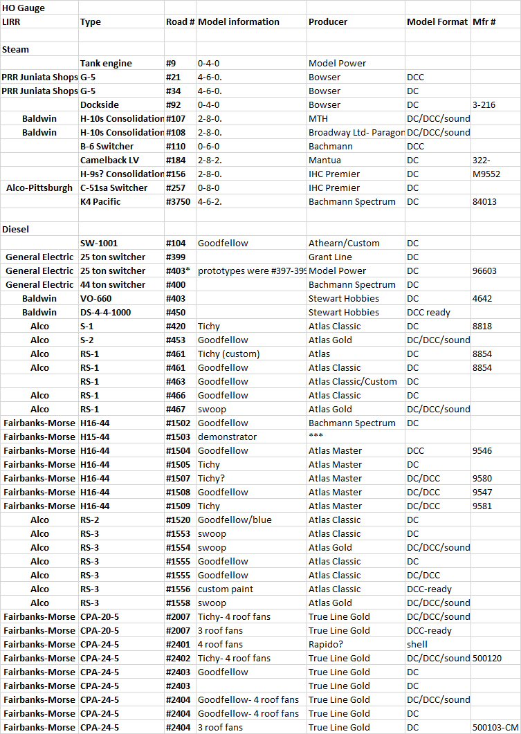 HO LIRR - Steam & Diesel |
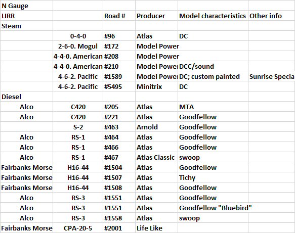
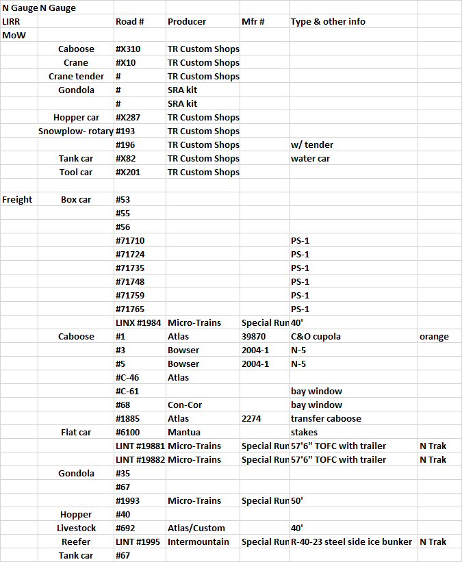 N LIRR - Freight & MOW
|
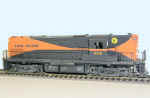
| A First Proto Scratch Build - GN Boxcar | |||
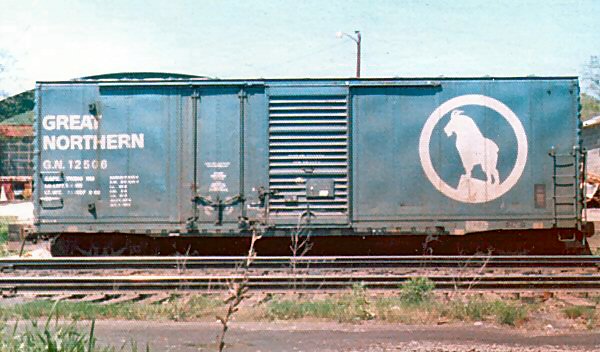 GN #12506 Boxcar plug/sliding door "Big Sky Blue" Oneonta, NY 3/1972 - Photo/Archive: Steven Lynch |
 GN #12003 |
Modeling this car began with an extended eBay/online search for a undecorated 50' plug/sliding door box. Having finally found one; the following was added:
1. Kadee couplers |
|
|
It's an early Spring day in late March 1972 at the Delaware & Hudson Railroad main classification yard in Oneonta, NY. Housed here were the engine shops/repair/rebuild facilities, a 180� roundhouse, major classification yard, etc. in days gone by. The yard at this time is in serious decay as many RIP tracks are full, the roundhouse is abandoned, and very few employees/activities are in evidence. This car, spotted further east of the main yard, was still in active revenue service and I found it intriguing; thus my first freight car photo. Steven Lynch |
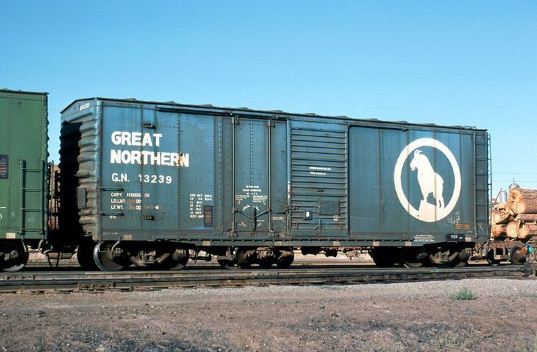 GN #13239 Double door - plug/sliding Klamath Falls, OR 8/2//1974 Photo: Ron Hawkins |
||
|
|
|||
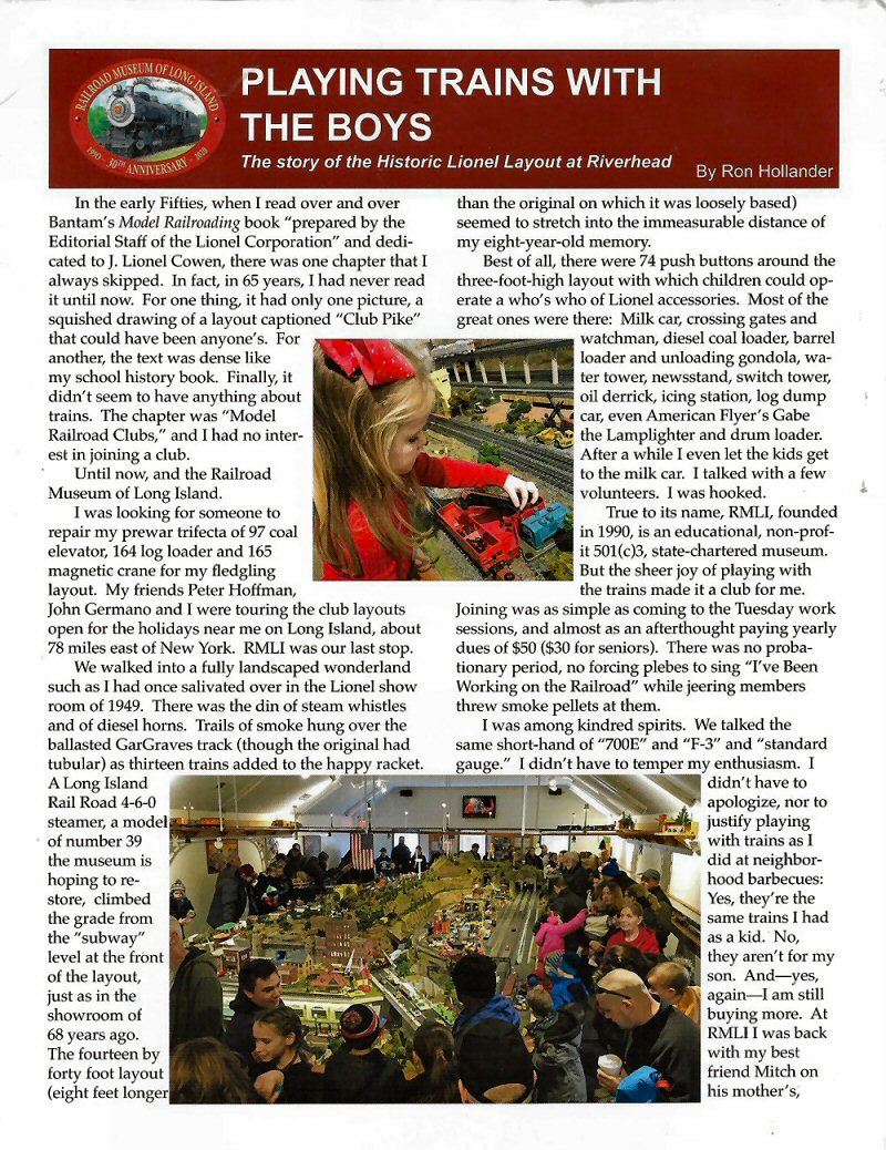 Playing Trains With The Boys - The story of the Historic Lionel Layout at Riverhead, RMLI by Ron Hollander 2019 |
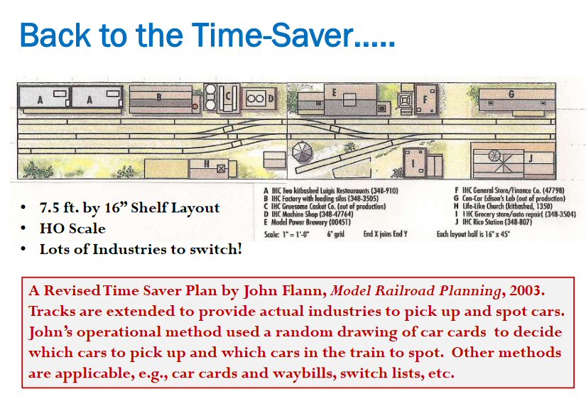 Model Railroad Planning 2003 - Timesaver
|
 Modeling from a Perspective Photo Model Railroader Feb.2022 page 51 by Wim Harthoorn |
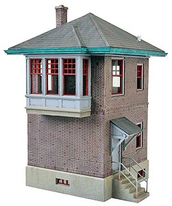 Walther's PRR/LIRR Interlocking Tower LIRR MODELER ARTICLES by Mike Boland 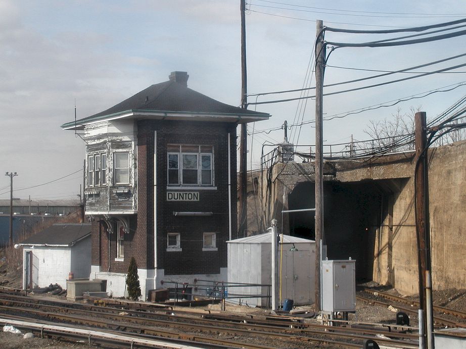 DUNTON Tower Photo: S. Thurmovik 3/30/2000 |
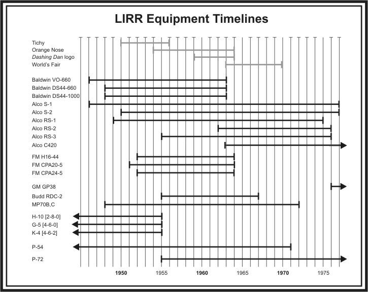 Chart/Research June 2007: Walter Wohleking published in Modeling Mineola |
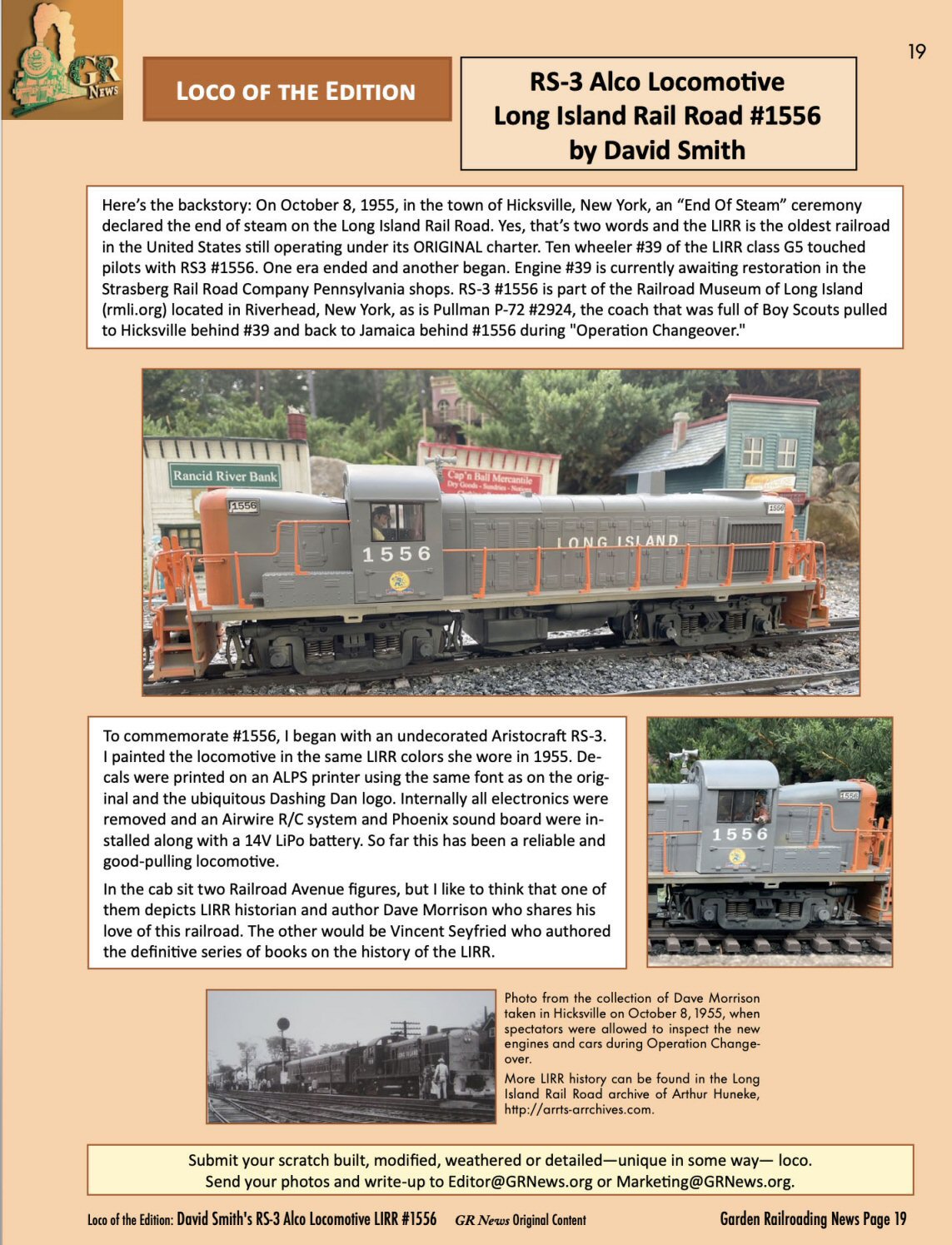 G Scale ALCO RS-3 #1556 Garden Railroading News by David Smith |
||
| LIRR Model Railroads | |||
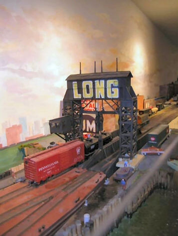 Nick Kalis' Lower Montauk Branch |
 Jim Caramore's LIRR - LI City to Morris Park  Art Single's LIRR Railroad |
 John Ciesla - LIRR - "The Eastport Branch"
|
 Glen Johnson's LIRR - North Fork |
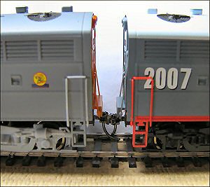 LIRR C-Liner Coupler Upgrade 6/18/2008 Text and Photos: Pat Scopelliti |
 Alco C420 smoke lifters - Atlas HO scale Model/Photo: Al Castelli |
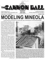 The CANNONBALL Spring 2005 Modeling Mineola - LIRR Mineola Site |
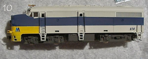 LIRR FA #614 6/18/2008 Text and Photos: Richard Glueck 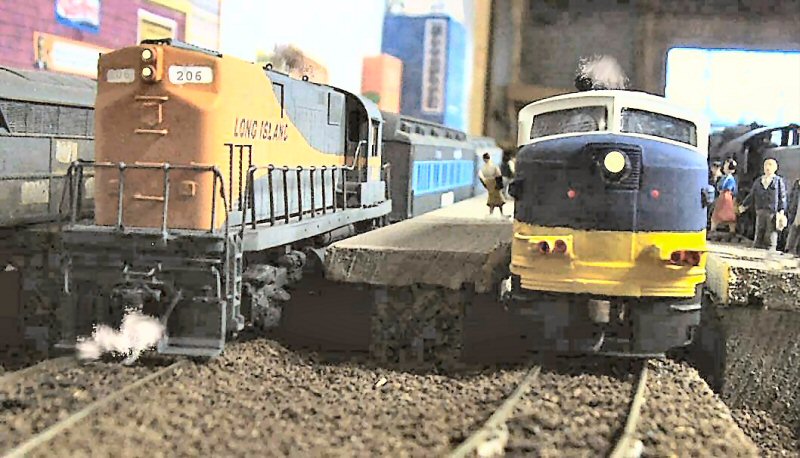 LIRR #206 C420 Walters FA-2 Models/Photo: Richard Glueck |
 Roslyn Layout Design Element (LDE) appeared in Model Railroad Planning 2004 |
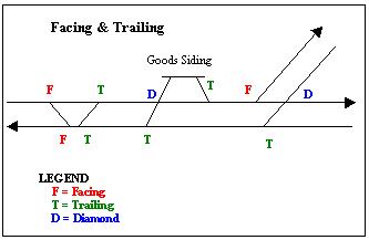
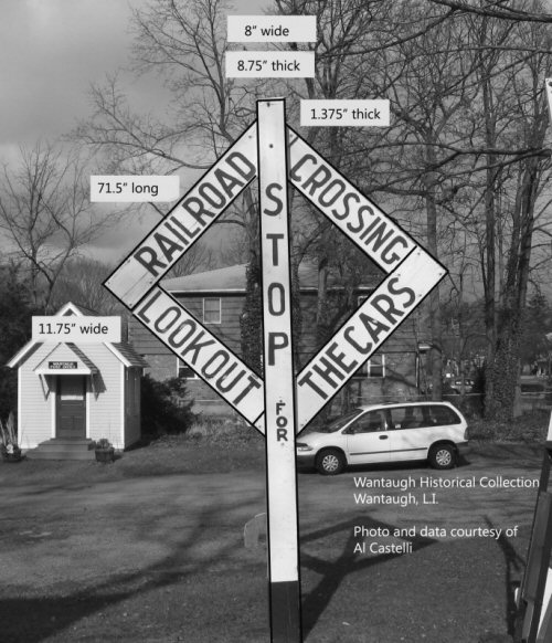 LIRR Diamond Crossing Sign - Wantagh Historical Society Photo/Archive: Al Castelli |
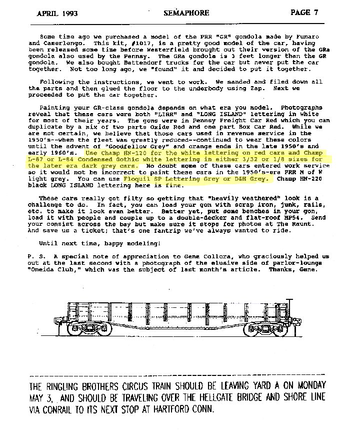
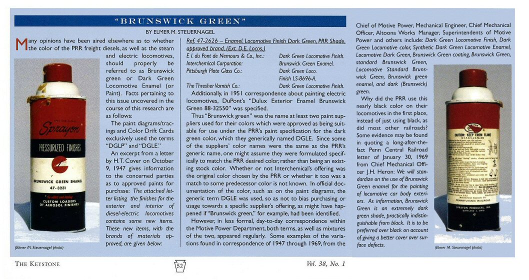
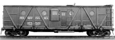 LIRR NX23A Hacks 07/05/09 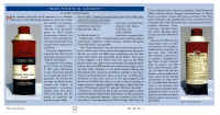 PRR Brunswick Green 06/23/08 from The Keystone Vol. 38 No.1 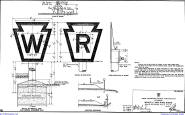 PRR/LIRR Whistle Post and Ring Sign Specs 1927 4/26/2005 |
 Richard Glueck's 1.5" to the foot, or 1/8th scale. LIRR N52A #43 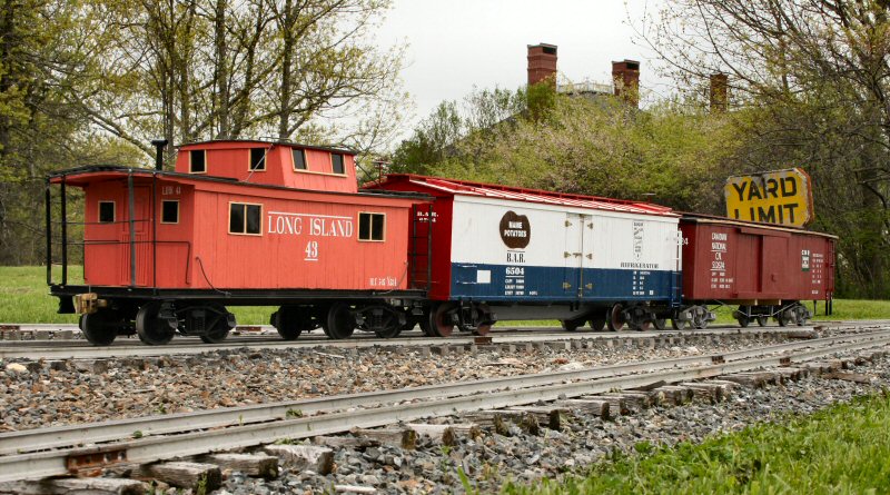 The BAR reefer weighs in at about 70 lbs. The CNR boxcar is filled with bricks, so it now weighs about 80- 90 lbs. The LIRR caboose is light, and weighs about 30 pounds. My locomotive weighs about 400 lbs. when loaded with water and coal; light it weighs about 300 lbs. Richard Glueck |
| LIRR Modeling
Articles - 5/30/08
Modeling the Long Island's Cannon
Ball by: Doug Nelson - MR October 2006
LIRR GP38-2 Article by: Frank Cicero
RMC Feb 1994 |
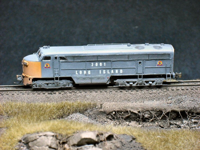 FM #2001 Z scale Photo: John Bartolotto
|
 LIRR C420 #200
LIRR Diesel Engine Units 05/30/08
|
|
|
|
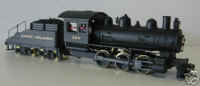 LIRR 0-6-0 Class B51-53b LIRR Steam Engines 6/18/2008
|
 LIRR N5 Caboose #1 LIRR Caboose' 5/30/2008
|
|
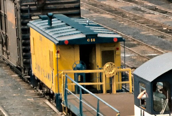 LIRR C-56 Roof Detail Photo: Henry Wagner |
 GE 44 Ton Diesel Switcher - Tsunami Soundtrack TSU-100 Mini-decoder Install |
 LIRR Freight Modeling 06/24/08 |
 LIRR Lionel Cars 07/17/2008 |
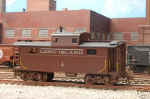
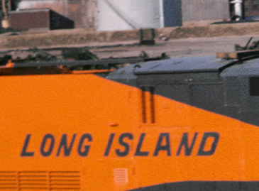
 LIRR N52/52A wood cabooses or cabin cars in the photo. The two in the
photo are in PRR cabin car red with white LONG ISLAND lettering; there are
no orange cabooses here. Also, this was apparently before the railroad�s
steel caboose fleet beginning with cabin car #50 arrived. So let me date
this photo between 1955 and 1958 although it may even be a little earlier.
LIRR N52/52A wood cabooses or cabin cars in the photo. The two in the
photo are in PRR cabin car red with white LONG ISLAND lettering; there are
no orange cabooses here. Also, this was apparently before the railroad�s
steel caboose fleet beginning with cabin car #50 arrived. So let me date
this photo between 1955 and 1958 although it may even be a little earlier.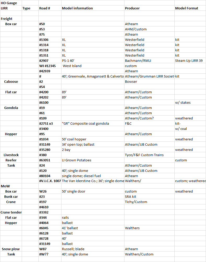


